

How to Choose One Assembly Fixture to Trial
When a small assembly tool is slowing production, the first question is not “Which 3D printer should we use?” It is “Which one fixture problem can we define, trial and judge?” A useful first project has a visible operating problem, a manageable load case and a clear pass/fail check.
At IMTS 2026, tooling and factory-floor applications were a focus of Stratasys’ announced demonstrations. Its September 10 release described plans for fixtures, manufacturing aids and production applications at the September 14–19 show in Chicago. With the event now over, the useful question for an Ontario business is practical: which repeatable operation in your own shop would justify a fixture trial?
Start with a recurring assembly step
Look for a step that repeatedly depends on a person holding, aligning, supporting or orienting a part. The fixture should address a real nuisance such as awkward access, inconsistent seating, a fragile support, frequent product variants, or a tool that must be rebuilt because the original geometry is undocumented. These are candidate applications, not claims that one tool design will solve them all.
- Assembly nest: support a housing or panel at defined contact points while an operator installs components.
- Alignment guide: position a drill, insert, connector or fastener relative to a known edge or interface.
- Inspection locator: hold a component consistently for a visual check or a defined go/no-go measurement.
- Handling cradle: protect a curved, painted or delicate part as it moves between operations.
A suitable first candidate has limited, understood forces; accessible contact surfaces; an available mating part or sample; and a check you can perform at the workbench. If failure could injure someone, compromise a safety function, or damage expensive equipment, the validation and risk controls need to match that consequence.
Define the trial before designing the tool
Write down the operation in order: how the part arrives, how it is loaded, what must locate, what the operator does, and how the part is removed. Mark the interfaces that control the result. A fixture that merely holds a component is not necessarily locating it correctly; the actual datums, clearances, clamp direction and access for hands or tools matter.
Then set acceptance checks that can be observed: does the part seat without rocking, do the critical features align, can the operator complete the intended step without forcing or damaging the part, and can the tool be removed without trapping the assembly? If the process involves drilling, milling or meaningful clamping loads, those forces require engineering analysis and a suitable safety review before a printed tool is considered.
Formlabs’ manufacturing-aids guidance recommends checking a printed fixture against its CAD and testing how the workpiece seats under clamping. It also points to practical design choices such as ribs, ergonomic grips, inspection faces and adding standard components where useful. Its guidance flags creep under sustained load and suggests metal or hybrid construction for high-wear areas. See Formlabs’ jig and fixture guidance.
Use the right route for the job
Additive can be a fit when a tool has unusual contours, needs iteration, serves a low-volume or changing application, or would benefit from integrated geometry. A machined plate, standard clamps, replaceable pins or a hybrid frame may be better where loads, wear or dimensional stability dominate. For simple flat profiles or repeated high quantities, conventional machining or dedicated tooling may be the stronger choice. Compare the complete job, including design, finishing, assembly, inspection and expected replacement needs—not just the printed part.
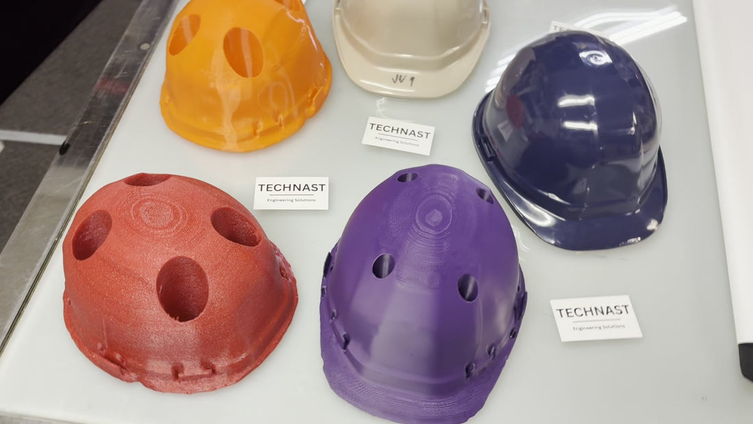
In that project, TECHNAST inspected the real shell, developed geometry through scan and mesh data, iterated the design, selected dense TPU for controlled compliance, and checked the tool against the physical shell. The published evidence shows visible flex, recovery and fit. It does not establish a lifetime multiplier or helmet certification. Each fixture needs its own requirements and verification.
What to send for a fixture assessment
TECHNAST can assess a custom assembly fixture through inspection, measurement or scanning where useful, CAD development, process selection, a prototype and physical fit or function checks. Start with a description of the operation, key dimensions and mating interfaces, load direction, heat or chemical exposure, quantity, acceptance criteria and deadline. Tell us what photos, CAD or physical samples are available; TECHNAST can confirm the appropriate transfer or inspection route. Note what currently goes wrong and how operators recognize a good result.
For BO-002, contact TECHNAST about one assembly-fixture candidate and mention the reference. The team can review whether additive, a hybrid design or another manufacturing route makes sense. See engineering-led 3D printing services and 3D scanning and reverse engineering for the related workflows.


